")
")
Installation manual
DataDisplay BMW E9X
Current status: 2018-02-21
Disconnect the battery before installation!
Installation is only to be carried out by qualified personnel!
1 Delivery content
- Display with frame
- Harness for Controller & Junctionbox
- Displaywire
- 1x Housing (white) for displaywire
- 1x USB Wire (for updates)
- 2x Housings (black)
2 Required tools
- Depending on the vehicle Torx T20 or 8 / 10mm ratchet
- Plastic wedge (optional)
- Small flat-head screwdriver or paperclip (to pin out the contacts)
3 Disassembly
3.1 Disassembly the interior trim
The following parts have to be removed:
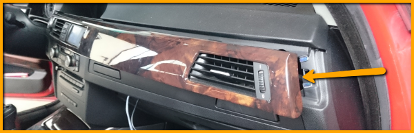
- Interior strip - The fresh air vent is attached to this
- Fresh air vent- This must be disassembled so that the display can be inserted with the frame
- Cover under glove compartment (passenger footwell)
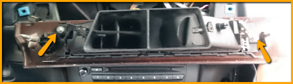
First, the interior bar on the front passenger side is levered off. A plastic wedge or lever facilitates the work.
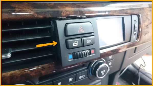
Lever out further in the direction of the steering wheel. Attention: The start/stop button and the switch unit on the fresh air vent are still connected to the interior trim by cables.
Disconnect the plug at the start / stop button:
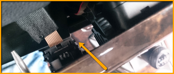
When the start / stop button is completed, the bar can be pulled out a little bit further.
Disconnect the connectors of the switch unit.
Fresh air vent from below:
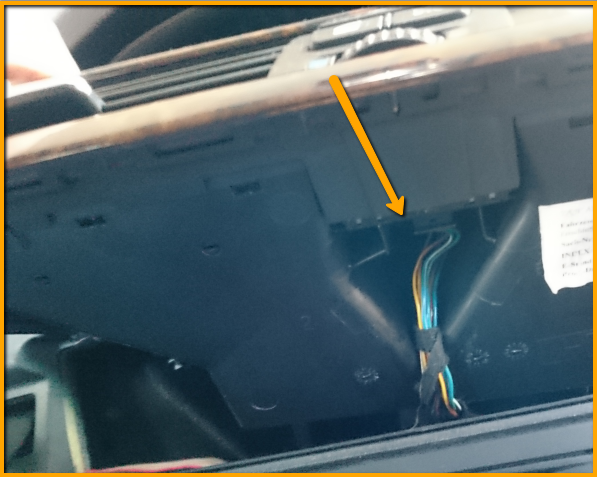
For some models, the switch unit can now be pushed out from back to front (i.e. E91). For others (i.e. E92), the fresh air grill must first be disconnected from the interior trim (next item).
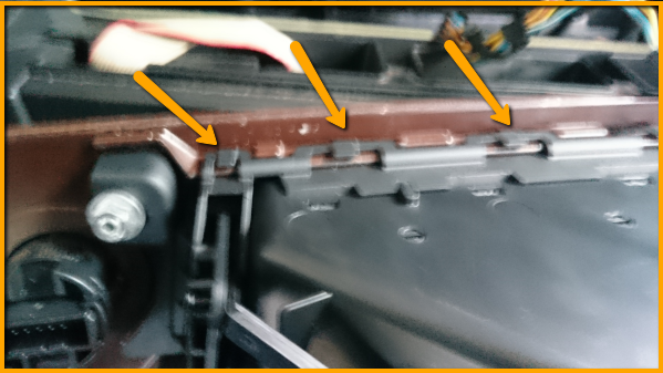
The fresh air vent is attached to the interior trim with two 8mm nuts and several clips.
The two nuts are on the left and right sides.
The clips must be unlocked carefully with a flat-head screwdriver.
It helps to start from one side and push the vent from the interior bar.
3.2 Disassembly passenger footwell
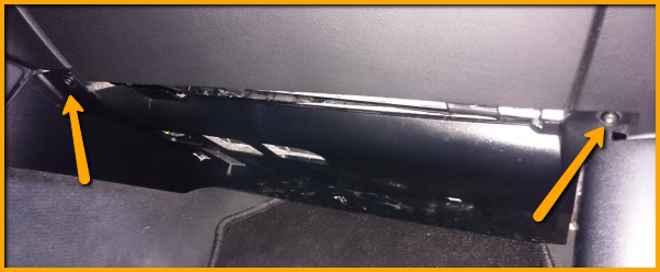
Now the cover can be removed under the glove box.
Usually there are two Torx T20 screws on each side which need to be removed.
Now the cover can be carefully drained. Attention, there is still a plug connection of the footwell lamp to separate.
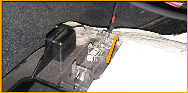
The way from the fresh air vent to under the glove compartment is now free and the display cable can be laid.
From which side (top to bottom or bottom to top) you start is up to you. The "open end" without the white housing has to be at the upper side.
On the right side of the opening, where the fresh air vent was, you can push the display cable down or thread from the bottom up.
4 Connection JunctionBox / Controller
Attention - because the display cable is "open" on one side, connect this cable ALL at the end to the controller! Short circuit!
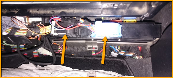
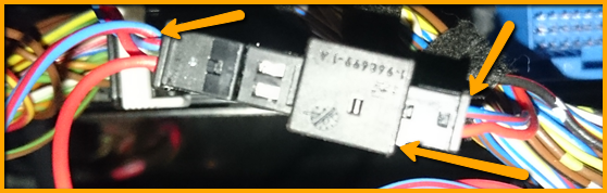
The JunctionBox is now freely accessible in the passenger footwell.
This one has a black and a blue plug.
The side on which the connectors are located (left / right) may vary.
However, the following always applies: The CAN bus on the blue plug must be connected to the controller and the power supply must always be on the black plug.
The cable colors from the wiring harness (Data Display Controller):
Red / yellow: power supply from JunctionBox (black connector pin 1)
Brown: Ground (GND) from the JucntionBox (black pin 6 pin)
Red / Blue: CAN_High from JunctionBox (blue pin 1 pin)
Red: CAN_Low from JunctionBox (blue connector pin 2)
Attention, the colors on the JunctionBox are 99% identical to those on the cable harness of the new controller. However, it can happen occasionally that the 12 Volt power supply is not red / yellow but has a different color. Here should be checked twice that the pin number is correct.
In vehicles without gps device, it may be that the pin 1 on the black connector is not used. In this case, it is merely pinned, nothing has to be pinned out here.
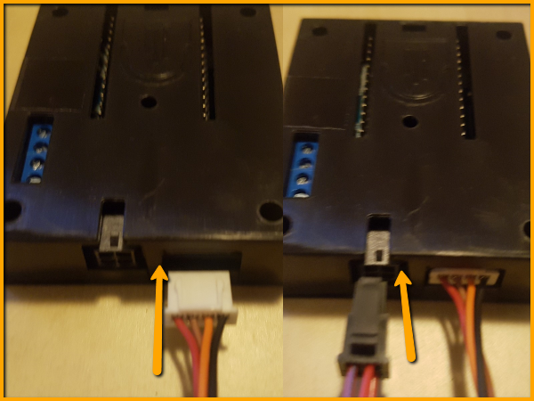
Picture here with black plug left and blue right:
Next, the blue plug is unlocked.
To do this, press the latch and fold the safety latch around.
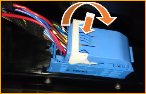
The plug is pressed out of the JunctionBox and you can pull it off.
To remove the connector housing, the sides must be pushed apart. This can be done with your hands or you can use a flat-head screwdriver.
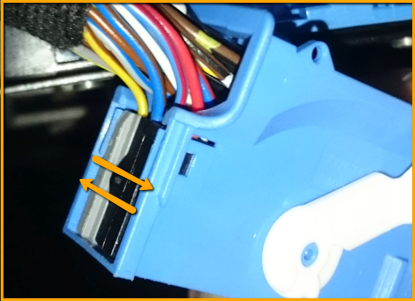
When pushing apart, carefully push the housing backwards so the plugs come out.
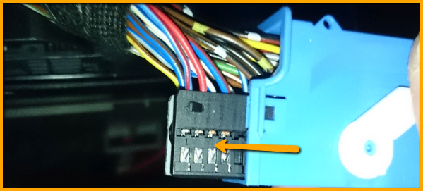
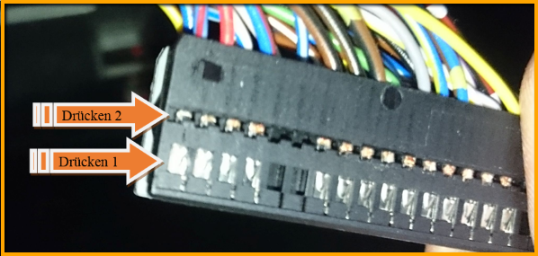
Now the cables Pin 1 (CAN_High with the color red / blue) as well as Pin 2 (CAN_Low with the color red) are pinned out. Use a small flat-head screwdriver, a needle or something similar. The crimp contacts have a flag which works like a barb. This flag must be pressed and at the same time carefully (!) Pulled on the cable.
Attention: the flag can snap in a second time in the intermediate opening. Here you have to press (Drücken 2) again.
As already mentioned, pin 1 is CAN_High and is plugged into the supplied socket housing.
It is important to ensure that the colors match the wiring harness when the connectors are connected.
CAN_High should be piped in on the right side (depending on the viewing).
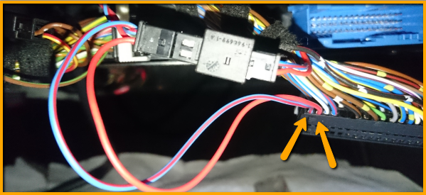
The open end of the wiring harness is pinned in place in the connector of the JunctionBox. (Pin1 = Blue / Red | Pin2 = Red)
When piecing in, you should make sure that the flag also locks in place - Applies to the supplied socket housing and the plug of the JunctionBox.
The controller is integrated in the bus circuit.
When this blue plug is done, the housing can be pushed back and plugged into the junction box. Fold the safety bar back and check the plug for tightness.
The power supply (black plug) is handled similarly.
Remove the black connector and housing.
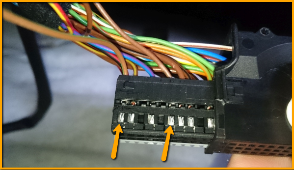
Pin 1 (in the following picture brown / green but in most cases red / yellow or red / white) is pinned and pinned into the supplied socket housing (right side - check compliance with the controller wiring harness!). The red / yellow cable of the wiring harness is plugged into pin 1 of the connector. It can also happen (especially if no navigation device is installed) that no cable is sitting here. So only the red / yellow cable of the DataDisplay must be plugged.
Pin pin 6 with the color brown and pin in the socket housing. The brown wire of the wiring harness is nipped in the same place.
If the contacts have been inserted into the supplied socket housing, the locking bracket must still be pressed until it snaps into place.
The black plug can be reconnected to the JunctionBox.
Attention, never plug the power supply to the CAN bus and vice versa!
The two plugs are now fitted to the cable harness.
Check again that the colors are exactly the same. If something has been done wrong here high costs can arise due to defective vehicle electrics!
Fresh air vent / display
The fresh air vent is already removed from the interior bar and the display cable with the open crimp contacts is at the top side.
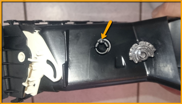
On the side of the fresh air vent are the levers for opening and closing the nozzles.
These must be dismantled so that the front panel can be removed in the next step. Here is a picture without the "bracket". To remove this, the "pivot point" must be compressed and the bracket removed.
The bracket and the sprocket usually have a white mark which must match again during later assembly.
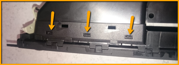
The next step is to separate the front panel of the fresh air grill from the case.
There are barbs at the top and bottom. These must be pressed with a flat-head screwdriver and at the same time carefully pulled on the front panel. Working from the outside to the inside!
If the front panel is removed, the ventilation slots are removed.
These can be unlocked simply by pushing them sideways and then remove them to the front.
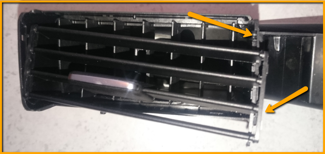
To remove the other part, the housing must be gently pushed apart.
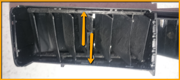
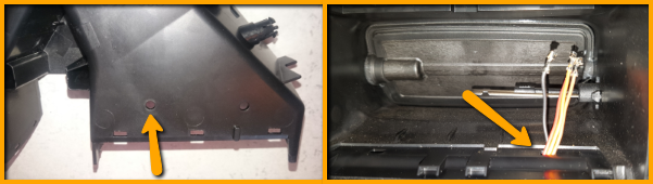
On the bottom are two small holes which are now free.
One of the holes is needed to pass through the 4 wires of the display cable one after the other. The fresh air grill does not need to be processed and remains 100% original for the rearm.
It is important to use the hole closer to the center of the grille, otherwise the length of the cable will be a problem.
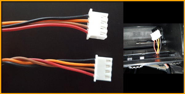
If the cables are plugged through (the easiest is one after the other, all together will not work through this small opening) the contacts are put into the white bushing.
Attention: The cable is 1: 1 occupied. Make sure that these are eingepinnt exactly like on the other side.
The front panel must now be plugged in again.
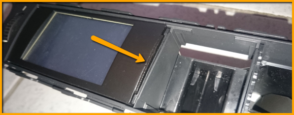
The display cable is now plugged into the display and can be plugged into the OEM intake points of the air duct.
To do this, the display is pushed from right to left in the direction of the adjustment wheel. It can help if you push with a blunt object from behind against the display.
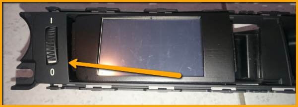
Then the right side is pushed into the OEM bracket.
The last step is the assembly.
- Push the switch unit (hazard lights, etc.) back into the fresh air grill unit.
- Clip the fresh air vent with the display back into the interior trim and secure it with the two 8mm nuts (hand-tight!)
- Connect switch unit and start / stop button
- Put the interior strip on the dashboard
The display cable and the controller can now also be plugged in. The guide lugs must point upwards.
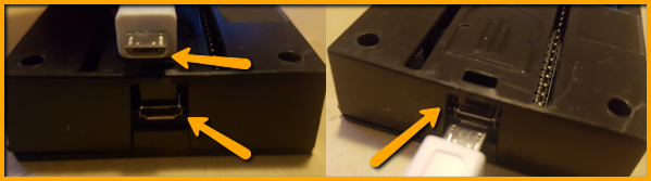
The USB cable for updating can be placed in the glove compartment from the back. So this is always up for updating accessible and well stowed.
WARNING: Plug in the plug only with caution and without force! Danger of breaking off!
The USB cable only fits one way into the controller.
If you try to plug it in the wrong way, the USB socket can break!
The bevelled corners of the plug must face down.
Close the cover of the passenger's footwell and stow the controller in a suitable position.
The DataDisplay by AK-Motion is now ready for use.
Have fun with it
5 Technical specifications
- working voltage 7V - 36V
- Current < 100mA (0mA after vehicle standby about 30-60 minutes after shutting off)
- current consumption 1.0A@12V
- input 12W
- Display Output: 5V
- Temperature range -40°C bis +85°C
- weight ca. 100g
- Dimensions 52 x 52 x 25 mm (B x H x T)